The MicroSquirt® Module is designed to be a Do-It-Yourself starting point for your own custom Engine Management System (EMS). Since you will be using the module in your own applications and most likely spinning up your own PCB to host the module, it makes sense to take a look at extending the base functionality of the module. Nowadays its real easy to do this with all of the custom ICs and modules that are readily available. Also, the CAN connectivity of the MicroSquirt® Module allows you to easily access the realtime data within the module in order to develop custom hardware implementations. The module does the hard part of engine controls, allowing you to focus on the FUN stuff!
The following are a few circuit ideas that may be used to extend functionality or enhance the module to make it even more robust.
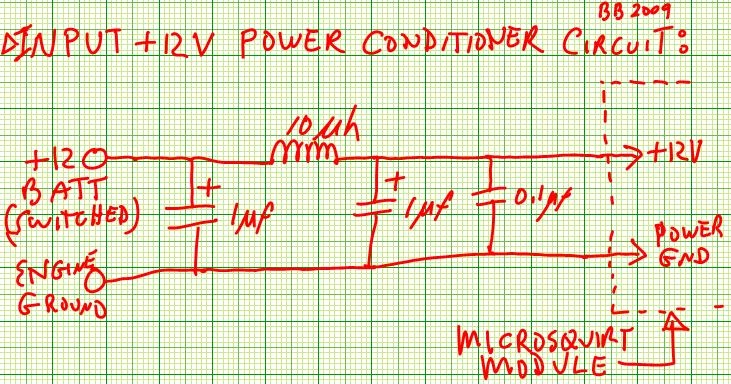
The MicroSquirt® Module contains input voltage protection and some filtering. In some cases additional filtering may be desired in order to reduce effects of nasty effects like alternator whine, starter noise, etc. The first line of defense is, of course, proper installation techniques like grounding to engine block with multiple parallel wires (reduce inductance effects), supplying a low-impedance path for the +12V input, etc.
If you desire additional supply voltage filtering, the following circuit can be used. The capacitor/inductor arrangement provides filtering to spike noise. Be sure to use high-voltage rated components since vehicle voltage can swing +/- 40 volts or more. Try to use non-polarized caps if available. The +12V supply is of order of 120 ma, so the series inductor can be small in size.
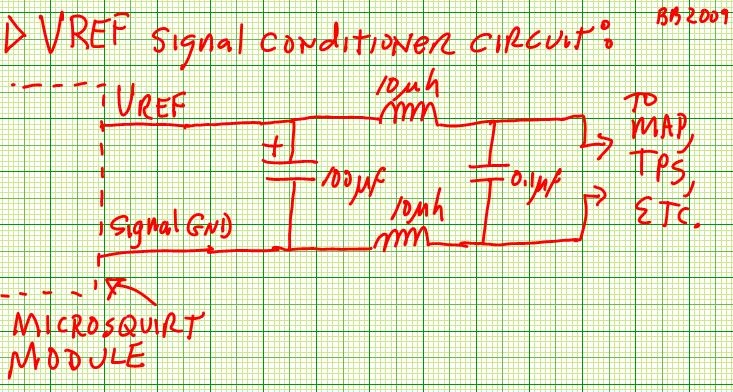
There are some external sensors which require 5 volts to operate, namely the MAP, MAF, and TPS sensors. This reference voltage is generated in the Module and supplied externally thru the Vref signal and Sensor Ground. In order to maintain ratiometric processor ADC operation the same supply is used for both ADC reference and sensor power. This means that there is a possibility of noise coupling back in from the Vref signal to the Module.
The circuit below shows a possible filtering arrangement for Vref. First off, adding a large capacitance on Vref will help make it steady and also keep the Vref line stiff at 5V. Anything from 47 microFarads to hundreds of µF can be used. Next, a simple inductor/capacitor arrangement can be of help. Since there is very little current draw on the sensor ground and the Vref supply is stiff, adding inductance here is not an issue. You can also substitute a pre-made EMI filter like the Murata BNX002-01 filter here if desired.
OK - serial ports on laptops are pretty much history. USB connectivity is king. And, its easy to add USB with the interface chips out there from Prolific, FTDI, Silicon Labs, and TI. These chips create a "Virtual COM" port arrangement on the PC over USB - the PC thinks its connected to a regular old COM port but the data is actually transmitted via. USB. Sounds great..
But, since USB is higher speed compared to UARTs (a.k.a. serial port) noise in an automotive environment can be an issue. Additionally, the signalling from the MicroSquirt® module is RS-232 signal levels (+/- 12 volts), not TTL level, so level translation is required. So, lets kill two birds here and come up with an isolated USB interface.
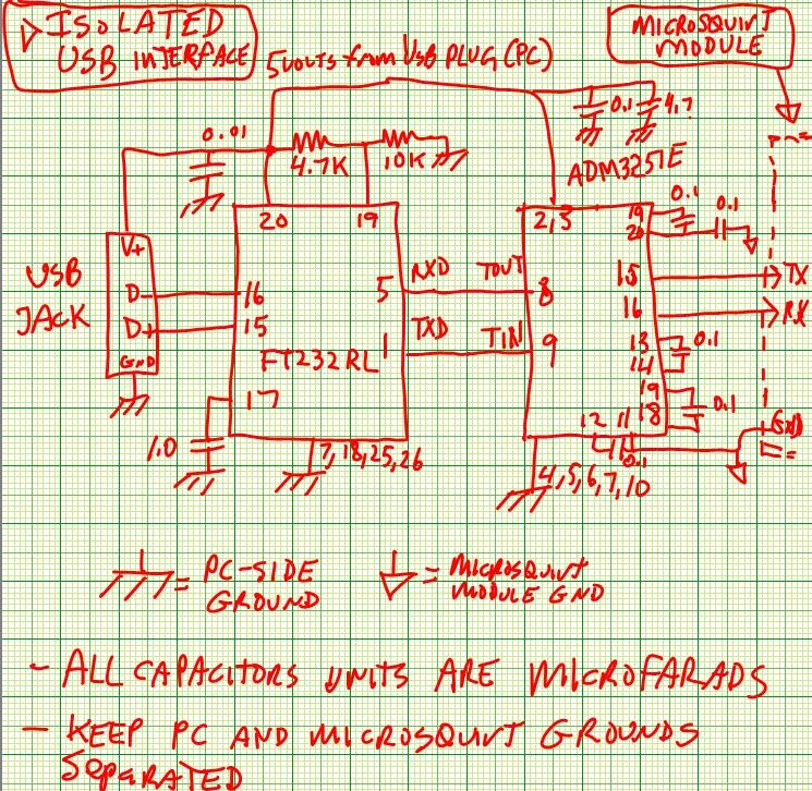
A very popular USB-to-serial (TTL) chip is the FTDI FT232RL. This part handles the USB-to-serial translation, signal coding, etc. And its possible to power this chip direct from the USB, meaning that the chip is powered directly by the PC via. USB cable. Five volts runs thru the cable (limited to 500ma) and it can be used to provide power.
Very recently, Analog Devices has released a UART level translator (i.e. RS-232-to-TTL) that is completely isolated! The ADM3251 interface device. There are little transformer inside that couple the signals so that they remain isolated. It also has a built-in DC-DC converter to generate the +/-12 volts needed for the RS-232 side (this is the side that connects to the MicroSquirt® Module).
So, combining the two we have the circuit below. Note that the FTDI chip and half of the ADM3251 operate off of the PC's power supply. There are reports that the FTDI chip can operate in this mode just fine, so its being used like this here. Additionally, since the PC is supplying the power to the FTDI chip the Virtual Com port software (on the PC) will stay assigned to the same port, even if power is cycled on the module end. The +/-12v for the RS-232 signalling is generated by the ADM3251 device.
NOTE: I have not tested this circuit, so be sure to verify operation yourself...